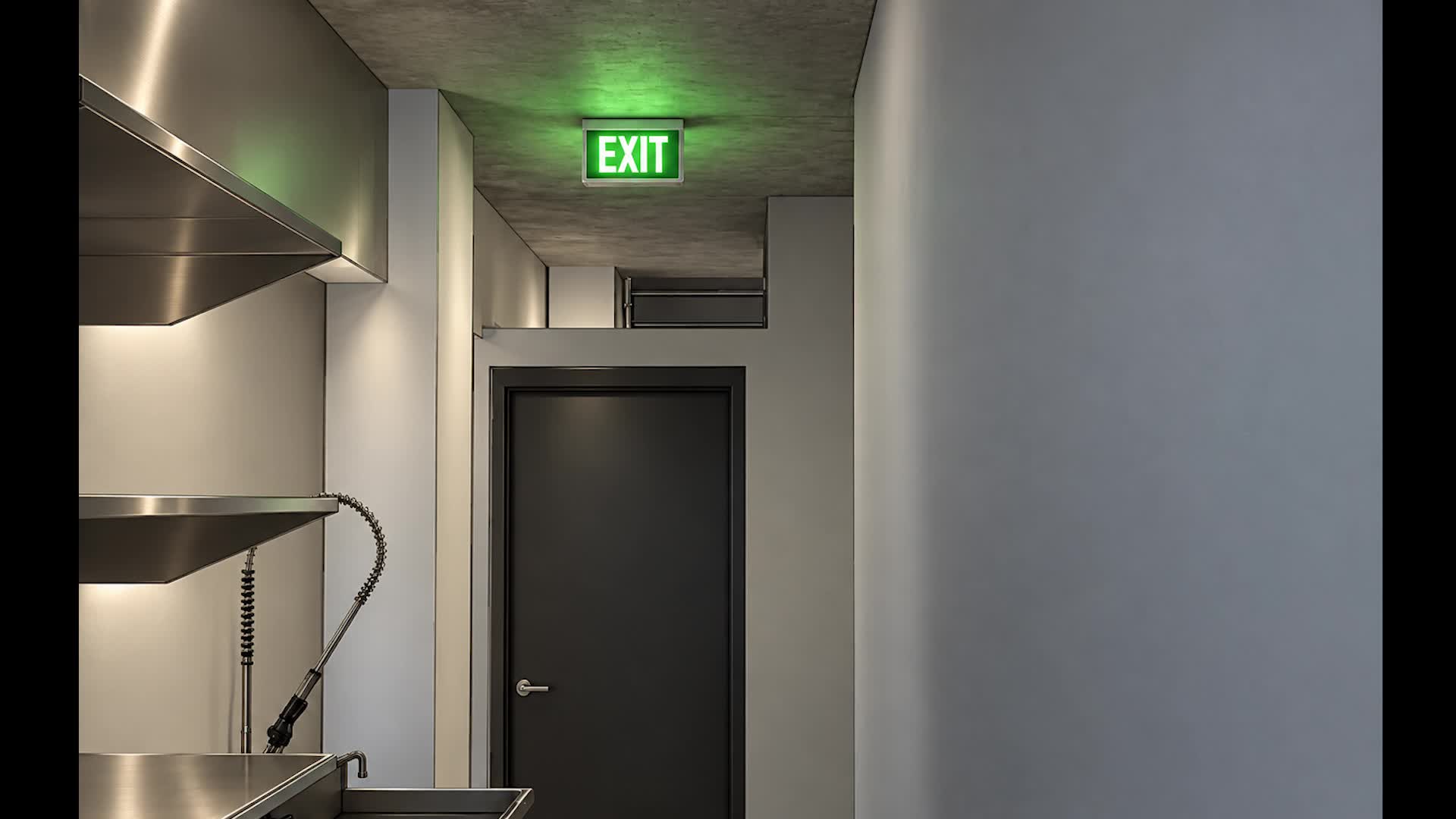
An EXIT sign looks like a simple object: some lettering, a backing and a recognizable material. Building it as a Revit family, though, means deciding how to organize the geometry, control its dimensions and place it in the project.
The Short shows this workflow in 60 seconds. It's a sped-up edit of the work, with the rendered result at the start and at the end. Here we look at what the steps shown represent and why they matter.
Reference planes: structure first#
The work starts with reference planes. They are the guides that organize the component: they let you define axes, alignments and limits before you focus on the visible shape.
The session log shows the planes being created, dimensions being added and equality constraints being turned on, marked EQ. Their job is to keep the relationships between parts consistent while the sizes change.
Dimensions and parameters: giving measurements a meaning#
A dimension can be more than a number to read. In the recorded process, family parameters are created and the Family Types dialog is used to adjust the values.
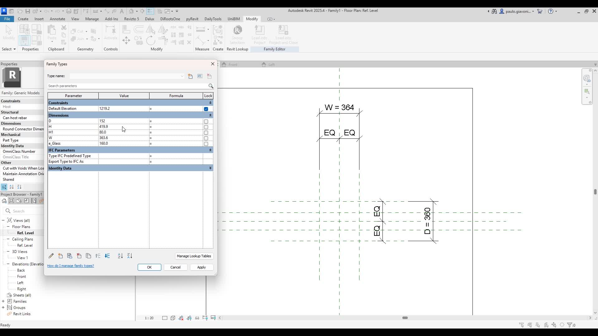
The key step is linking the dimensions to the structure of the component. A useful family must be controllable without redrawing the geometry every time. The edit summarizes these operations; it doesn't contain every click needed to reproduce them.
Geometry and text: building the sign#
The session continues with solid extrusions, rectangular profiles and constraints. That's how the component gains volume. The lettering joins the composition too, and its position relative to the backing needs attention.
Legibility has to be checked together with the shape: it isn't enough for the text to exist in the model, it needs a clear placement when you look at the object in different views.
Materials and finishing#
In the video, the Material Browser marks the move from geometry to appearance. Choosing materials helps tell the parts of the sign apart and sets up the visual result shown in the render.
Then come adjustments and checks on the component. The green lettering in the final result makes the sign instantly recognizable in the context of the space.
From the family model to the project#
The 3D view gives an overall reading of the volume, orientation and position of the parts. The log then records the family being loaded into the project and the component being placed, with further work-plane operations.
This is where the detail stops being an isolated object: it has to find a consistent position in the model. The final rendered image shows the visual outcome of the process.
Step-by-step guide: build your own EXIT family#
This exercise follows the logic of the recorded session and offers a simple version you can recreate. The parameter names and sizes below are teaching values, not a transcription of the original settings. The session was recorded in Revit 2025, and the command names below match the English interface you see in the video.
1. Create and save the family#
- In Revit, choose File → New → Family and open the Metric Generic Model template from the template library.
- Save it as Segnale_EXIT.rfa. Work in millimeters: check Manage → Project Units.
- For this first version, keep the family non-hosted: you'll build the vertical sign in the Front elevation and place it in the project using a level and an offset.
What to check: in the Project Browser you'll find the reference level, the elevations and the 3D view. This template is for the geometry exercise; a lighting fixture family would need its own category choice and settings.
2. Sketch the skeleton in the Front elevation#
- Open Front. Treat the reference level as the base of the sign and the central vertical plane as the axis of symmetry.
- With Create → Reference Plane, draw one plane to the left and one to the right of the central axis, then a horizontal plane above the level.
- With Aligned Dimension, dimension left–center–right as a string and turn on EQ. Add an overall left–right dimension and a dimension between the level and the top plane.
What to check: the sides stay symmetrical. Don't add a second fixed constraint that forces a distance incompatible with the same string.
3. Turn dimensions into parameters#
- Select the overall horizontal dimension and, in the Label field, choose Create Parameter. Name it Width, pick a type family parameter, with data type Length.
- Repeat for the vertical dimension with the name Height.
- Open Family Types and set Width = 300 mm and Height = 150 mm.
- Temporarily try 400 and 200 mm, click Apply, then go back to the starting values. The planes should move without errors.
A dimension becomes a control for the family when you give it a label: see Autodesk's instructions on dimensioning reference planes.
4. Create the body of the sign#
- Still in Front, set a vertical work plane parallel to the view, for example the center front/back plane available in the template. Use Set Work Plane and show it to check its orientation.
- Choose Create → Extrusion. Draw a rectangle between the side planes, the level and the top plane.
- Align the four edges to the references with Align (AL) and close the padlocks. Avoid duplicating constraints that are already in the sketch.
- Set Extrusion Start = 0 mm and Extrusion End = 10 mm, then finish the sketch.
- Open the 3D view: you should see a vertical sign with thickness. If it shows up as a horizontal slab, fix the work plane before moving on.
5. Control the thickness and flex the geometry#
- Select the extrusion and use the Associate Family Parameter button next to Extrusion End to create Thickness, a type parameter of type length.
- Keep the start at zero and set Thickness = 10 mm in Family Types.
- Try width 400 mm, height 200 mm and thickness 15 mm. Check Front, Right and 3D, then restore 300 × 150 × 10 mm.
What to check: the solid changes, not just the dimensions. If Revit reports unsatisfied constraints, undo the last change and check the padlocks in the sketch. Autodesk calls this check flexing the family parameters.
6. Add the EXIT lettering in 3D#
- Set the visible face of the sign as the work plane: choose Pick a Plane and select the face in 3D.
- Use Create → Model Text and type EXIT. Use model text, because the lettering must be visible in 3D too.
- In Edit Type, duplicate the type before changing it. Set a simple font and a starting height of 60 mm; give the text a depth of 1 mm in the available properties.
- Look at the sign head-on and center the lettering with Move, using the references as a guide. Check in 3D that the letters stand out from the face and read from the correct side.
In this basic version the text has a fixed size: after changing the width or height of the sign, check the centering and margins again. The lettering doesn't adapt automatically just because the rectangle is parametric.
7. Assign the materials#
- Open Manage → Materials and create two clearly distinct materials, for example a dark EXIT_Supporto and a light green EXIT_Testo.
- Select the body of the sign: in the Material property, assign the backing material. Repeat on the text with the second material.
- To make the choice editable in Family Types, associate the Material property with the type parameters Materiale_Supporto and Materiale_Testo.
- Check it in a Shaded or Realistic view. For the render, edit the material's Appearance tab as well: the graphics color and the rendered appearance are not the same setting.
The modeled sign is complete even without a glow effect. The glow and lighting in the final render depend on the rendering engine, the materials and the scene lights; the green color alone doesn't create them.
8. Add a frame, if you want to refine the model#
The original session also includes a Sweep after a few undone attempts. It's an optional detail: finish and check the simple version first.
- Choose Create → Sweep → Sketch Path on the front plane and draw a closed rectangular path around the sign.
- Finish the path, switch to Edit Profile and open a view suited to the plane perpendicular to the path.
- Draw a small closed profile, for example a 3 × 3 mm rectangle, near the profile origin. Finish the profile and the sweep.
- Assign the material you want and check the corners in 3D. If you change the sign's sizes, check the frame path too: to make it follow automatically, you need to constrain it to the same references.
9. Load and place it in the project#
- Save the family and open the target project.
- In the Family Editor, choose Load into Project.
- In the project, use Architecture → Component → Place a Component, select Segnale_EXIT and place it in plan.
- Set the correct level and adjust the offset from level in the properties to lift it above the door. Use Rotate to turn the face toward the reader and Move/Align to fine-tune its position.
- Check the result in elevation and in 3D. If the family is changed, save it and reload it to update the one in the project.
The recording also shows the work plane being picked and flipped. These commands relate to how that particular family is placed: to reproduce them you need a work plane-based family. In the non-hosted version of this exercise, use level, offset and rotation instead.
10. Check before calling it done#
- The sign changes size without constraint errors.
- The text is visible and legible in 3D, on the correct side.
- The text and backing materials are easy to tell apart.
- The sign has the correct orientation, height and position above the door.
- After reloading, the project shows the updated version of the family.
Common issues: invisible text → check the work plane and the face; geometry not following the dimensions → check the locked alignments; lettering past the edge → reduce the text type or increase the sizes; different material in the render → check the Appearance tab and the scene settings.
Watch the process in one minute#
The video walks through seven stages: references, dimensions, modeling, materials, finishing, 3D check and placement in the project. Treat them as a map of the work in the Family Editor: first you organize the relationships, then you build and refine the shape.
The result is a small component that helps people read the space. Watch the Short below to follow the path from drawing to project. The video is in Italian.
The full video is on YouTube: if you enjoyed it, subscribe to the channel and hit the bell for the next episodes.
Questions or comments?
Questions about the videos and the book are welcome: write to me, or comment under the video on YouTube.
On LinkedIn I post every video from the channel, with a few extra lines.